You press your PC’s power button and nothing happens. Not a single fan spins and no LED lights up. Before blaming the motherboard or replacing components at random, the first thing to do is check the power supply unit (PSU).
With a simple paper clip and an inexpensive multimeter, you can check for yourself whether your PSU is dead or delivering the correct voltages. The process takes ten minutes. It involves simulating the PC’s startup to measure the outputs of the 24-pin ATX connector, as well as the 12 V, 5 V and 3.3 V rails.
Prepare your equipment on a clear surface, unplug the tower’s mains cable and follow these steps to confirm the diagnosis.
1. Use a PC ATX and ITX power supply tester
Unlike a technical diagnosis, this tool offers you a fast, accurate and safe way to check the health of your PC power supply. In just a few seconds, it measures the voltages of the various connectors and identifies any anomalies. No more dismantling or guesswork: this tester gives you reliable results directly via a digital display.
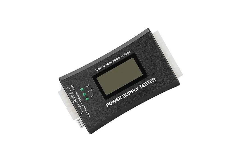
Highlights :
Drawbacks :
On Amazon right now:
How to use a PC power supply tester?
- Disconnect your power supply from the PC.
- Connect the power supply cables to the tester (SATA, IDE or ATX as required).
- Switch on the power supply and let the tester do the rest. If there is a problem, a warning LED or an error message will be displayed.
With this tester, you can quickly check whether your power supply is still performing correctly or whether a replacement is necessary. It is an essential accessory for any computer enthusiast or technician looking for reliability.
2. Test your PC’s power supply with a paper clip
Is your PC failing to start or shutting down for no apparent reason? Before you panic or spend money on a new power supply, there is a simple and inexpensive way to check whether it works: test it with a paper clip and a voltmeter. Yes, a paper clip can become your ally when diagnosing your PC.
No expensive equipment is required. Here is everything you need:
- A paper clip (yes, the one in your drawer).
- A voltmeter or multimeter (it is always useful to have one at home).
Prepare the power supply: disconnect it completely from your PC and take the main connector, the 24-pin one.
Group all the power cables and connectors together to simplify the tests. Keep them as far away from the case as possible. Place the open, disconnected case in a convenient location, such as a table or a flat, non-static surface, to make handling easier.
Short-circuit the power supply with a paper clip to start it
Short-circuit pins 15 and 16 of the motherboard’s 24-pin power connector (see the diagram below) using a small piece of wire or a paper clip. This connects the green pin (Power On) to a black pin (Ground).
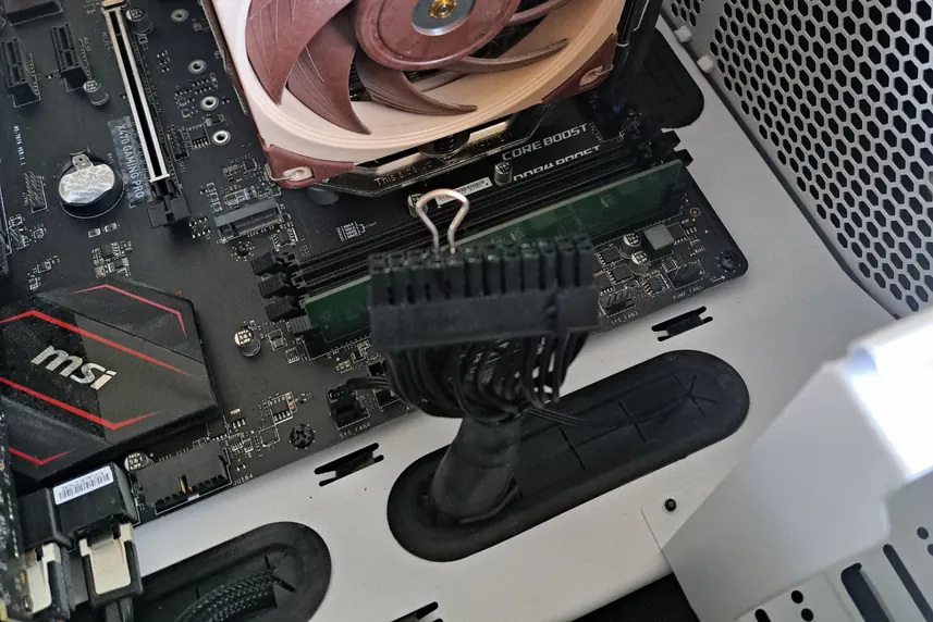
Then switch on the power supply and check that the fan is running
Once the paper clip is in place, reconnect the power supply to the mains and turn on the switch, if it has one. If the fan starts, the power supply is activating correctly. You can then continue measuring the voltage with a voltmeter.
If the fan still does not turn
If your power supply’s fan does not start after you bridge the pins with the paper clip, you may be using a modular power supply. Some modular power supplies include safety or energy-saving systems that prevent them from starting fully when there is no load. In this case, connect an HDD to one of the available power cables. This creates a minimum load and triggers normal operation.
If the problem persists, the power supply may be faulty and need to be replaced.
In that case, you may need to recalculate the power required by your PC.
Measure the voltage with a voltmeter
Turn on your multimeter and set it to VDC (DC volts).
Test the motherboard’s 24-pin power connector by placing the negative probe (black) on a ground pin (15, 17, 18, 19 or 24), then the positive probe on pin 23 (5 V – red).
A reading between 4.8 V and 5.2 V indicates correct operation.
ATX 24-pin 12 V power connectors
You can also check the different voltages delivered by the pins of the 24-pin ATX connector with a multimeter to make sure that your power supply is working correctly.
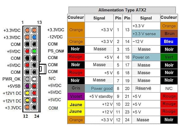
Possible multimeter tests for a 24-pin 12 V ATX power connector:
- +12 V pins (yellow, pins 10 and 11)
Test the +12 V pins. A correct reading should be between 11.4 V and 12.6 V. - +5 V pins (red, pins 4 and 21)
Check the +5 V pins. Normal voltage is between 4.8 V and 5.2 V. - +3.3 V pins (orange, pins 1, 2 and 13)
Check the +3.3 V pins. A correct value is between 3.14 V and 3.47 V.
If the measurements do not match or show significant fluctuations, this may indicate a problem with the power supply. In that case, we recommend replacing it to avoid damaging other components in your PC.
| Pin | Signal | Colour | Voltage |
|---|---|---|---|
| 1 | +3.3V | Orange | +3.3V |
| 2 | +3.3V | Orange | +3.3V |
| 3 | COM (Ground) | Black | 0V |
| 4 | +5V | Red | +5V |
| 5 | COM (Ground) | Black | 0V |
| 6 | +5V | Red | +5V |
| 7 | COM (Ground) | Black | 0V |
| 8 | Power Good | Gray | +5V |
| 9 | +5V Standby | Violet | +5V |
| 10 | +12V | Yellow | +12V |
| 11 | +12V | Yellow | +12V |
| 12 | +3.3V | Orange | +3.3V |
| 13 | +3.3V | Orange | +3.3V |
| 14 | -12V | Blue | -12V |
| 15 | COM (Ground) | Black | 0V |
| 16 | PS_ON# | Green | ~0V |
| 17 | COM (Ground) | Black | 0V |
| 18 | COM (Ground) | Black | 0V |
| 19 | COM (Ground) | Black | 0V |
| 20 | Reserved (N/C) | N/A | N/A |
| 21 | +5V | Red | +5V |
| 22 | +5V | Red | +5V |
| 23 | +5V | Red | +5V |
| 24 | COM (Ground) | Black | 0V |
ATX 24-pin 12 V power connector pinout (ATX v2.2)
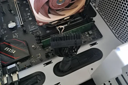
The 24-pin connector is the largest power connector on your power supply unit (PSU). It consists of 24 pins arranged in two rows of 12.
It is connected to the right-hand side of the motherboard, near the RAM modules. This connector powers the main motherboard.
If you have several cables in front of you, remember that the 24-pin ATX connector is the one with the most pins and fits into a clearly visible rectangular port on the motherboard.